Stylophone retro pocket synth
Содержание:
- In Use
- Step 5: The Circuit Board
- What did the Stylophone 350S sound like?
- Introduction: A Stylophone
- Stylophone 350S switching explained
- Step 10: Testing
- Step 1: That 555 Is Connected Is a Way That Is Weird!
- Step 6: Etching
- Step 2: The Output Amplifier
- Step 12: Parts List
- Step 3: The Tone Resistor Bank
- The GEN X‑1
- Step 8: Mounting the Components
- What was different about the Stylophone 350S?
- Conclusion
- Step 7: Solder Plating the Keys and Drilling the PCB
- The Stylophone Beatbox
In Use
Unlike the original Stylophone, which was powered by a single PP3 battery, the GEN X‑1 is powered by four AA batteries. The difference isn’t as inconsequential as it sounds because the choice of the PP3 made it simple to use mains power — you just used a 9VDC converter with a PP3 header. If you nibbled a small hole in the case, you could even make the connection inside the instrument, whereupon the mated connectors or a knot in the cable provided stress relief so that you could use it on stage as well as in more clement environments. Regrettably, there’s no such simple solution for the GEN X‑1, and you would have to perform more radical surgery to obtain the same outcome. (I asked the chaps at Dubreq whether there’s any plan to add a power input, but they said that there isn’t.) The batteries should last for a few hours but, if you leave it switched on after the soundcheck, there could be tears during the gig.
 The bottom of the GEN X‑1 houses a recessed tuning knob and the battery compartment. The plastic case of the GEN X‑1 is slightly larger and heavier than the original and the S1, but it seems no more robust so it will be important to treat it with care; I doubt that it will survive a fall onto a concrete floor nor any other form of serious mistreatment. The additional size allows for the control panel to co‑exist with the speaker on the top panel, but has another important consequence — the ‘keyboard’ is four semitones wider than before, making it just a single semitone short of a two‑octave C‑to‑C device. As I was soon to discover, the extra few notes make a significant difference when playing. Mind you, it remains quite tricky to play the GEN X‑1 well, not because the interface requires great skill, but because getting a clean contact between the stylus and the metal keyboard is not always straightforward. Failing to do so causes the pitch to glitch and, unless you’re into such things, renders the performance unusable. But, once you’ve got the hang of sliding the stylus between notes, things improve rapidly. I found that adding four rubber feet to the underside of the case also helped with this, stabilising it and making it unnecessary to hold it with my left hand while playing.
Lying behind the keyboard, there’s a strip of plastic that looks like nothing more than a graphic affectation, but this turns out to be one of the instrument’s most interesting features. Called the Soundstrip, this is nothing less than a ribbon controller that allows you to play the GEN X‑1 using your fingertip. It’s not quantised, so you can slide between notes and, with a suitable wiggle, create vibrato. Unfortunately, the strip is recessed within the case and you need to press it hard to hold notes and to stop the sound retriggering as you glide between pitches. It seems that the chaps as Dubreq were concerned that the prototype strip was not robust enough, especially if played using the stylus, so they made it tougher (which made it less sensitive) and recessed it to protect it. If I were allowed to ask the people at Dubreq for just one improvement, it would be to lift the strip up to the level of its surround and make it more sensitive again. (OK, maybe that’s two improvements.) In fact, I did ask, and they told me that they already planned to look into this at some point. If this were sorted out, the GEN X‑1 could become irresistible for some players.
Rather than test its sound using its internal speaker, I hooked the GEN X‑1 up to a full PA system and discovered that it generates a far deeper and more powerful sound than you might expect. Almost inevitably, I started by emulating Claviolines, and soon found myself playing Telstar and other classics of the era. Imitating sounds such as strings and brass proved to be beyond it, not least because the GEN X‑1 suffers from the same note on/note off thump that characterised its ancestor, but I could obtain an interesting range of slightly noisy leads and basses without any difficulty. Mind you, the noise levels increased dramatically when I used the delay line, which also exhibits aliasing if you play high pitches. (No, it’s not digital; analogue delays also suffer from aliasing.)
Initially, the review unit suffered from a couple of faults; the lowest pad on the keyboard (bottom C) wasn’t reliable and, more significantly, the outputs from the sub‑oscillators were inconsistent, leading to glitching as they cut in and out. Fortunately, both faults improved quite quickly; the pad became more reliable as time passed, and I tracked the sub‑oscillator problem down to the knobs in the Envelope section — after a few moments of sweeping these from side to side to improve their internal contacts, all was well.
Step 5: The Circuit Board
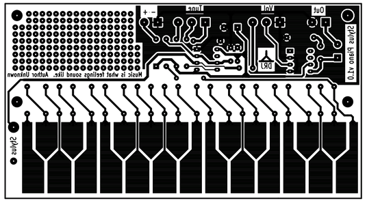
I laid out a PCB that I could use Toner Transfer to etch — It even has space for a prototyping area so I can extend the project at a later stage.
Again — It is single sided, and the layout was simple enough that I didn’t need to use any jumpers.
Don’t use the PNG file here — it is just to show you the layout — use the PDF file for making your board. As you will see soon, the PNG file is backwards for our uses — the PDF is correct, and will make a beautiful board!
Now for the tricky bit — The layout is designed so that the copper is ON TOP of the PCB — not underneath — It would be a very boring project if we had to put the stylus under the board to play it. I decided to design the board so that the components are still mounted on the top, which is the COPPER side of the board — We will discuss that soon — but first — To the etching process.
What did the Stylophone 350S sound like?
With so many shiny new features, the Stylophone 350S was always going to have a sound of its own. While it still retained buckets of the original Stylophone charm, it had a unique sonic character that set it apart.
The extended keyboard range meant more notes at your disposal then ever before. By adding the additional voice options into the mix (voiced across 4 octaves themselves) you were presented with a huge range, from deep fuzzy bass to sparkling trebly leads.
Speaking of extra voice options, you could combine up to 4 of the voices together for all manner of quirky textures. By using up to 4 octaves at once, the 350S offered a far more complex, rich sound that was still bundles of fun.
Introduction: A Stylophone
By drj113Follow
More by the author:
About: I have a background in digital electronics, and am very interested in computers. I love things that blink, and am in awe of the physics associated with making blue LEDs.
More About drj113 »
I was browsing through the Instructables technology area the other day looking at musical circuits, and I noticed that there was a project that was missing… The good old fashioned Stylophone.
There are a couple of wonderful examples that were there in the spirit of the original (with even better features), such as the Tic Tac Tunes , and the NoiseAxe Minisynth, but I couldn’t find an original PCB based keyboard, using good old fashioned analog electronics.
So I made one!
This Instructable will show you how to make your own original stylophone — The schematic that this is based on is my own, so it is free from Intellectual property restrictions. It is based around a 555 timer (so it could be an extension of the recent «Know Your 555 timer» article), and uses an ubiquitous LM386 audio amp so it can have enough volume to stand out from the crowd.
As with all of my projects, the PCB is designed for etching yourself, and there are no components that are difficult to source — in all, the Stylophone can be constructed for less than about $30AUD.
There is a breadboard area on the PCB, so you can add your own tremolo, or even an AtMega168 chip if you feel inclined. Allowing you to create the ultimate in digital analog fusion!!!! (Sorry — I couldn’t resist) 🙂
Update: I just downloaded a video onto youtube. Click here to view it.
Stylophone 350S switching explained
- Photo — choose the effect that the Photo Control is assigned to — either waa waa or vibrato (explained in more depth below).
- Decay — as it sounds. Choose between a long or short decay.
- Reiteration — as mentioned above, this is controlled by the second stylus. It’s essentially a note repeater, with a slow or fast setting.
- Vibrato — again as it sounds, similar to the original Stylophone. Slow and fast settings to choose from.
- Woodwind — 4 woodwind-like voices, each tuned an octave apart and displayed like organ stops (16, 8, 4 and 2).
- Brass — 2 charming voices reminiscent of a trumpet, set an octave apart (16 and 8).
- Strings — 2 confident voices set an octave apart (4 and 2).
Step 10: Testing

To test the board, I connected a speaker to the output, and applied power using a 9v battery.
Woot! — The first thing that I noted was there was a distinct lack of smoke coming from the board — that was an awesome step forward… (if there is smoke, remove power then find out what happened…)
Because there was no smoke, I touched the stylus to the keyboard, and was immediately rewarded by a cool electronic sound. Sliding the stylus up and down the keyboard, I found that the note altered in pitch, and that the pitches were pretty close to what I wanted! YAY.
The volume worked as expected, and the tuning control altered the tuning as well.
I was really pleased with the serious electronic sound from the plastic coned speaker that I purchased. That’s what I wanted!!!! In all a great day!
Step 1: That 555 Is Connected Is a Way That Is Weird!
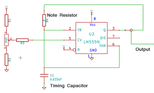

The heart of this project is the wonderfully versatile 555 timer, configured as an Astable Oscillator (An oscillator that continues to provide output pulses as long as it is turned on.)
If you look at the circuit for the original Stylophone, you will see that the 555 has a diode and transistor hung off the discharge line (pin 7). These additional components ensure that the output waveform has a duty cycle of 50%.
In a standard configuration, a 555 allows for the timing capacitor (C) to be charged via R1 and R2, but discharged using a separate discharge pin (pin 7) only via R2 — this means that the cap charges using one path, and discharges using a different circuit path, resulting in an output that may not spend equal amounts of time being High and being Low This is especially true when one of the resistors is being changed to change the tone.
I will admit that I am unsure why the original designer was worried about the duty cycle — remember that this instrument produces square waves — they are a *rich* source of harmonics..
I found a cool way of connecting the 555, that ensures that the duty cycle is 50% using a much simpler configuration here. Essentially, the oscillator is connected so that the normal 555 discharge connection is not used. Instead, this circuit uses the output pin to both charge, and discharge the timing capacitor, ensuring that the duty cycle is kept at 50%.
The frequency of oscillation can be adjusted by varying the voltage on the Control Voltage pin (Pin 5) — this allows the Stylophone to be tuned to other instruments.
Awesome!
Step 6: Etching
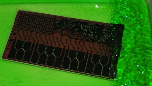


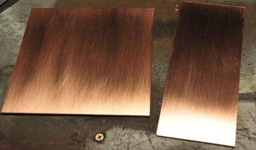
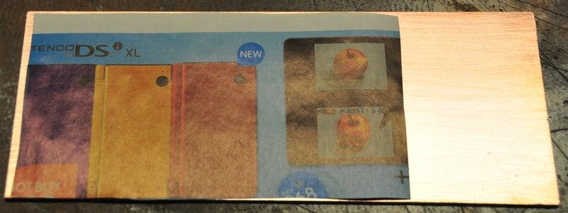
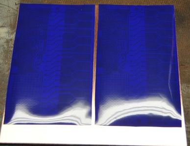


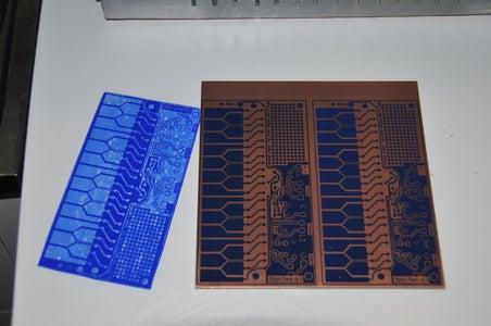
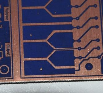
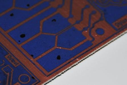

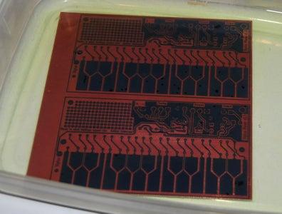
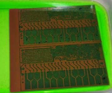
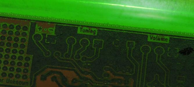

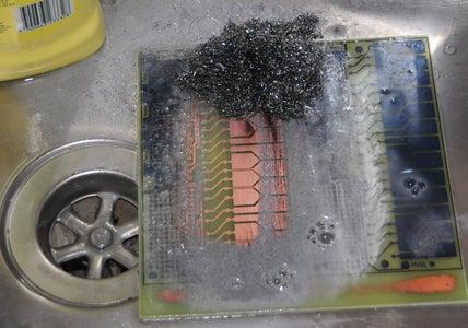
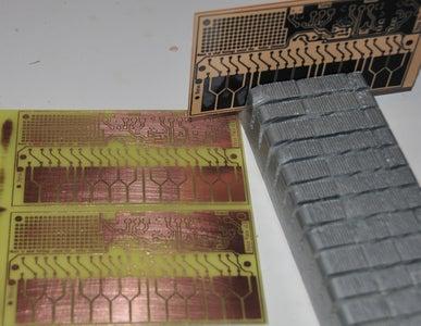
If you have kept up with all of my instructables so far, you should know how I etch boards by now. I will include the detail here if you need the information.
I personally use Cupric chloride as my etchant, and toner transfer as the resist method — It does not cost very much, and I can make a ton of projects from the scrap press-n-peel left over from my clock kits 🙂
Normally I would just use press-n-peel film, but because people have been telling me that printing onto catalog paper also works, I decided to try that as well. So — I printed the layout onto both transfer mediums.
I decided to make two boards — one for my dad, as a present to replace his Stylophone I destroyed as a child, and one for me, so it was a wonderful opportunity to try both methods.
Next, I used my laminator to bond the toner to the PCB ready for etching — I use a temperature of about 170 degrees C (At least that’s what the display says).
Press-n-peel: After the board cooled, I peeled the film off, and examined the layout for any spots where the toner didn’t bond properly — I just use a permanent marker to touch up the layout so that all of the tracks are well formed. I find that dust is my worst enemy. If I have been able to keep the workshop clean, things go really well, but if the place is grubby because I have been too busy, then I get spotty transfers.
Catalog Paper: I let the board cool, then I sat the board into warm water till the paper lifted off — I used my finger to gently remove the fibers that stayed behind. This time, I didn’t have to deal with spots on the layout.
Once I was happy with the layout — I placed the boards into the etchant — 150ml of 6% Hydrogen peroxide mixed with 75ml of Hydrochloric acid (for cleaning bricks). With continuous agitation, the board etched in about 4 minutes. As with any etching process, use caution with chemicals — protect your body using appropriate safety gear, and protect your work surfaces. The etchant will damage your stainless steel sink if you let it. this quantity will comfortably do 2 or 3 complete 6″ x 6″ boards
Once I was happy that the boards had finished etching, I placed them in a rinse bath to stop the acid from eating the copper. While rinsing, I took one of the boards and scrubbed the toner from it using steel wool. Both of the boards got a good rinse for about 5 minutes, when they were taken out and dried.
Step 2: The Output Amplifier
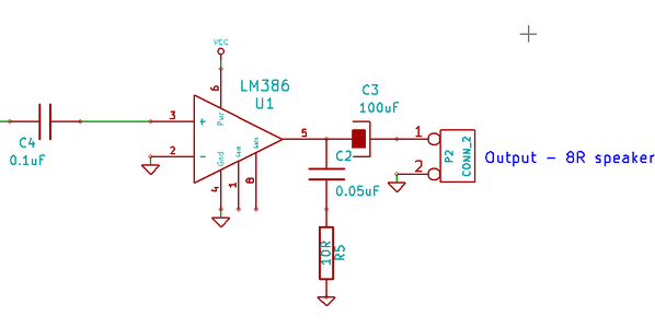
The original Stylophone did not have a separate output amplifier, instead, it relied on using a speaker that had a high impedance (75 ohms) so that it didn’t overload the output of the 555 chip. These high impedance speakers are tricky to obtain now, so I decided to use an 8 ohm speaker. Because 8 ohms is too low for the 555 to drive properly, I decided to use a separate amplifier.
Here is the output amplifier — it is based on the LM386 small audio amp chip, and provides a ton of output into either a speaker, or a set of earphones. If you do use earphones, be careful of your hearing — this will drive the headphones at a very high level….
The input capacitor (C4) is used to provide some isolation between the 555 timer output, and the amplifier input., and the capacitor / resistor combination (C2 & R5) is used to prevent the amplifier from self oscillating, which these chips love to do!
Step 12: Parts List
Here is the full list of components that I took to Jaycar.
Capacitors:
1 x 0.033uF Polyester
1 x 0.05uF Polyester
2 x 0.1uF Ceramic
2 x 100uF 16V Electrolytic (I substituted a 22uF tantalum for one of the electros, as I couldn’t fit it into the space properly.)
Resistors (all 5% tolerance or better)
1 x 10R
1 x 560R
1 x 1k0
2 x 1K5
1 x 1K6
2 x 1k8
1 x 2k0
2 x 2k2
2 x 2k4
2 x 2k7
2 x 3k0
2 x 3k3
1 x 3k6
2 x 3k9
2 x 4k3
2 x 4k7
1 x 24K
Semiconductors:
1 x 1N4004 Diode
1 x LM386 Audio Amp
1 x LM555 timer
Miscellaneous:
2 x 8 pin machined pin sockets
1 x 4k7 linear potentiometer
1 x 10K log potentiomener
Hookup wire
1 x 9v battery snap
1 x 9v battery
1 x 8 Ohm 2″ speaker
1 x mono output jack (1/4″)
Ballpoint pen for a stylus
Banana Plug for the stylus
Instrument wire (500 strand) for the stylus lead
Enclosure:
Perspex sheet 12″ x 12″ or wood. Sadly, not an Altoids tin!
Step 3: The Tone Resistor Bank

The single thing that makes a Stylophone unique is that the output note is selected by touching a stylus against a piano like keyboard. When the stylus makes contact with a key, a resistor is selected that corresponds to the required note. In my design, the entire chain of resistors selected is the resistance that is used to select the note.
It is important that the resistors are selected correctly so that the notes approximate those of a musical keyboard. With a keyboard, the notes have the following frequencies;
C — 261Hz
C# — 277Hz
D — 293Hz
D# -311Hz
E -329Hz
F -343Hz
F# -369Hz
G -392Hz
G# -415Hz
A -440Hz
A# -466Hz
B -493Hz
C -523Hz
C# -554Hz
D -587Hz
D# -622Hz
E -659Hz
F -698Hz
F# -740Hz
G -784Hz
G# -830Hz
A -880 Hz
The frequency that the 555 oscillates at (for CMOS versions) can be calculated from the following equation:
F = 1 / ( 1.4 R C )
In my circuit, C = 0.033uF (0.033 x 10⁻⁶) — I made a spreadsheet that calculated the total resistance needed for each note, and came up with this set of total resistances, which can be made using 5% resistor values:
C — 83360 Ohms
C# — 78660 Ohms
D — 74360 Ohms
D# — 70060 Ohms
E — 66160 Ohms
F — 62260 Ohms
F# — 58660 Ohms
G — 55360 Ohms
G# — 52360 Ohms
A — 49360 Ohms
A# — 46660 Ohms
B — 43960 Ohms
C — 41560 Ohms
C# — 39160 Ohms
D — 36960 Ohms
D# — 34760 Ohms
E — 32760 Ohms
F — 30960 Ohms
F# — 29160 Ohms
G — 27560 Ohms
G# — 26060 Ohms
A — 24560 Ohms
Using the resistances above, I calculated that the maximum theoretical error would be about 2 Hz from the desired frequency. In reality, the tolerance of the components (especially the capacitor) will make this error larger than that, so that will do.
I built a chain of resistors ( starting with 24.560k ) and incrementing by the required resistance as shown in the diagram so that when the stylus is connected to a note, the correct resistance would be provided.
When I tested the instrument, I was pretty pleased with the accuracy of the tones — It doesn’t match a digital instrument, but it is close enough.
The GEN X‑1
The newest incarnation was announced in 2017 and, rather than representing a further advance on the S2, this is designed as an original Stylophone on steroids. It boasts a single oscillator that offers a distorted pulse wave as the initial waveform, plus on/off switches for sub‑oscillators one and two octaves below the standard pitch, all of which can be activated simultaneously. There’s also a switch that claims to apply pulse‑width modulation to the standard pitch, but this didn’t sound quite like PWM to me so I hooked the GEN X‑1 up to an oscilloscope. Sure enough, switching PWM on doesn’t modulate the width of the initial pulse wave. Instead, it adds a second signal to the first and sweeps its frequency up and down at the rate determined by the LFO (which we’ll address in a moment). In other words, it adds a gentle chorus. The effect — both mathematically and sonically — is much the same, but it’s not PWM.
Tuning is accomplished using the traditional knob on the underside of the unit, but I think that it would have been good to relocate this to somewhere more accessible now that the Stylophone is more of a synthesizer than a toy instrument. Scaling across its keyboard is accomplished using a recessed trimmer reached through a small hole in the rear of the case. It’s just as well that this is accessible because, when I received the review unit, its pitch spanned just 22 semitones across the 24‑semitone keyboard. Happily, correcting this took just moments.
The output from the oscillator passes to a low‑pass filter that will oscillate at maximum resonance. This tracks the keyboard to a degree (not 100 percent, unfortunately) and can be swept using a contour generator that applies an AD contour to the cutoff frequency unless the Attack is non‑zero and the Decay is zero, in which case, after the Attack phase, the maximum level is sustained until you release the note. The same contour can also be directed to the oscillator pitch, and a knob then determines the amount by which it’s applied. In addition, there’s a square/triangle wave LFO that’s hard‑wired to both the PWM/chorus and the oscillator pitch; the Rate knob controls the frequency, while the Depth knob determines the amount of vibrato. (The depth of the chorus effect is fixed.) The final set of controls is for a delay line, with knobs for the delay time, the feedback amount and the overall level of the effect. The maximum delay time is a good fraction of a second, and the maximum gain of the feedback loop is greater than unity, so you can create the usual sci‑fi effects using this.
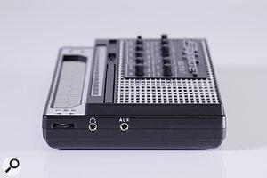 At the right of the unit is the volume control and 3.5mm socket for audio output and audio input.To the right of the unit you’ll find a volume control sitting next to a headphone socket that allows you to direct the Stylophone’s output to other equipment. There’s also an external audio input that, like the S2, allows you to use it as a signal processor. I suspect that, for some people, the GEN X‑1 could justify its price as an unusual lo‑fi filter/delay unit, although it doesn’t have the CV and Gate inputs of its larger sibling, so synchronised effects are beyond it.
Step 8: Mounting the Components
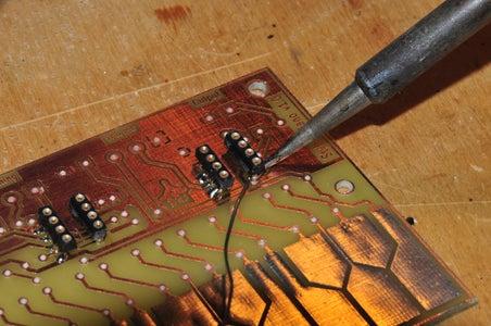

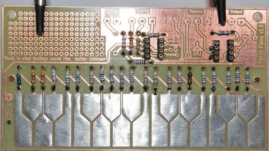
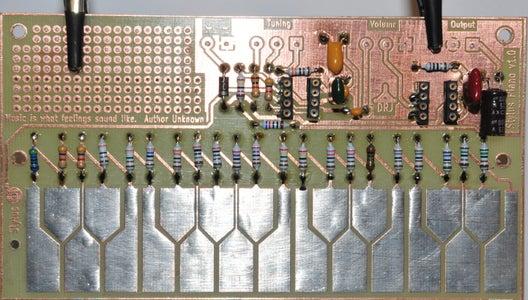
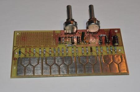
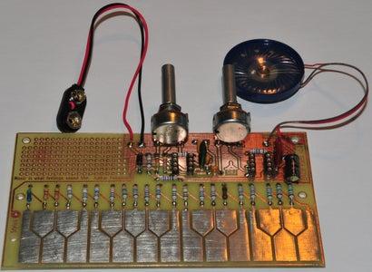
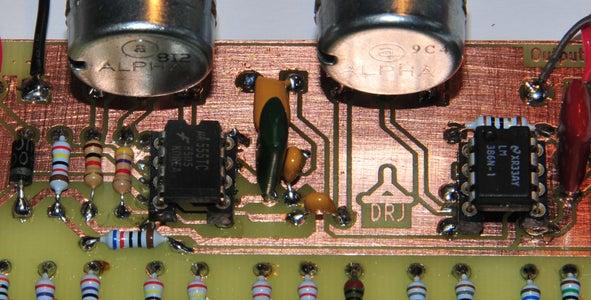
Remember when we discussed the PCB, I mentioned that the parts are mounted on the copper side of the PCB. I did this after I finished plating the keys.
The only tricky thing about this step was that I used MACHINED PIN sockets for the IC’s. I use this type of socket as they have a small ‘shank’ that causes the socket to sit proud of the PCB surface. This allows soldering to be done on the top side of the board. Just be careful not to melt the plastic with your soldering iron tip.
Next, I mounted the resistors, capacitors, and diode. When I mounted the electrolytic caps, I bent their leads to allow them to lie them down flat so that I could get to the leads under the package.
I finished by assembling the Volume and Tuning controls onto short cables, and soldered them to the pads on the PCB.
What was different about the Stylophone 350S?

First up: the size. As mentioned, the Stylophone 350S was considerably bigger than the familiar Stylophone instruments of the time — it remains one of the largest Stylophone varieties ever made. At over 6 times the size of the ’68 original, it wasn’t a handheld instrument in quite the same way.
With this increase in size came an increase in functionality. The familiar touch keyboard boasted a 44-note range — that’s a rather snazzy 3 and a half octaves compared to the usual 1 and a half.
Next up: 2 styluses are better than 1, as the old saying goes. Rather than simply allowing you to jump between notes across the extended keybed range, the second stylus (on the left) was used in conjunction with the ‘reiteration’ control. More on this later…
The larger enclosure combined with the extra feature set meant more power requirements — the 350S was fed by 2 PP9 batteries. Another reason for its increased thirst was the size of the loudspeaker behind that trademark wooden grill — a little extra volume never did any harm, right?
The final standout feature was the drastically-expanded set of controls. Those familiar with the Stylophone at the time will have been used to the Organ and Vibrato switches. The 350S instead featured an impressive array of rocker switches — here’s a lowdown of what’s what:
Conclusion
While it’s much more than a simple toy, the GEN X‑1 isn’t a substitute for a conventional synthesizer; rather, it’s a fun box that sits halfway between the original Stylophone and something more significant. As an oddity that you can pull out as a special feature on stage, or as a lo‑fi instrument or processor used to embellish recordings, it’s both fun and effective. If I was still playing psychedelic music, I would love to turn it on, tune it up, and drop it into the mix.
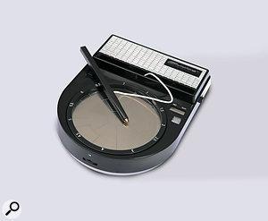 In addition to the S1, S2 and GEN X-1, Dubreq offers a percussion/bass instrument called the Beatbox. This offers 13 pads in a circular arrangement and you use these to trigger drum samples and vocal ‘beatbox’ samples, or to play synth bass. But it’s still based upon the Stylophone, so it’s monophonic and you can only trigger one sample at a time. It incorporates a recorder that allows you create drum & bass loops, although there’s no quantisation either upon recording or playback, so you’ll have to hone your skills to obtain anything useful. Like the GEN X-1, there’s a small built-in speaker and a 3.5mm audio output that allows you to direct the results to other musical equipment.
Pros
- It’s great fun.
- It’s much more flexible than the original Stylophone.
- The ribbon controller is an unexpected bonus, although it’s not as usable as it should be.
- It’s not expensive.
Cons
- It’s a bit noisy — and with the delay used, it’s more than a bit noisy.
- There’s no way to use it with mains power.
- It remains lightweight and potentially fragile — handle with care.
Summary
The GEN X-1 is more than a toy and, at the price, it could be fun to add one to your sonic arsenal. Whether you use it as an instrument or as a signal processor, just remember that it’s still a Stylophone and don’t expect too much of it.
Step 7: Solder Plating the Keys and Drilling the PCB

I left my board for completion later (when I finish this article), and decided to focus on Dads one. The nice dry board was then sprayed with a ‘solder through’ lacquer to prevent the copper from tarnishing. I protect the keypad area with some masking tape before I sprayed because I needed to solder plate the keys to protect them.
Next, I solder plated the keys. This was important to protect the copper surface of the keys from corrosion caused by contact with oily fingers and the environment.
I started by using a wide soldering iron tip, and some extra flux, and coated the keys with a thin layer of solder. Then, I re-fluxed the board, and used a hot air gun to smooth the solder down.
I was very careful not to overheat the board and de-laminate the keys. You may prefer to use some scrap PCB material to get the hang of it first.
A bit of abrasive kitchen cleaner and a steel wool scourer to clean up the keyboard area finishes the process. I think that the board came up really well.
Finally, the board was drilled using a combination of 0.8mm and 1mm drill bits. depending on the components that need to fit through the holes. I still use my trusty hand held Dremmel ™ tool which I have used for 20 odd years. It still goes beautifully.
Be careful with dust during the drilling process — use breathing protection.
The Stylophone Beatbox
 In addition to the S1, S2 and GEN X-1, Dubreq offers a percussion/bass instrument called the Beatbox. This offers 13 pads in a circular arrangement and you use these to trigger drum samples and vocal ‘beatbox’ samples, or to play synth bass. But it’s still based upon the Stylophone, so it’s monophonic and you can only trigger one sample at a time. It incorporates a recorder that allows you create drum & bass loops, although there’s no quantisation either upon recording or playback, so you’ll have to hone your skills to obtain anything useful. Like the GEN X-1, there’s a small built-in speaker and a 3.5mm audio output that allows you to direct the results to other musical equipment.
